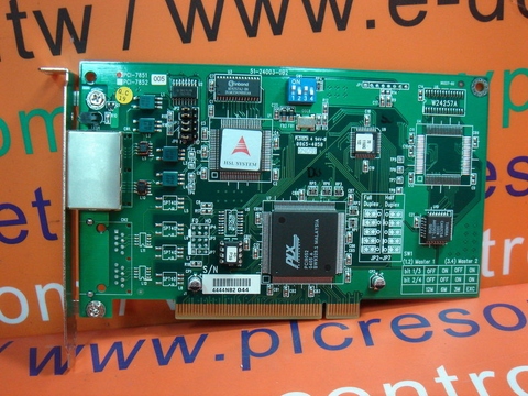
ADLINK HSL DRIVER

| Uploader: | Zolojora |
| Date Added: | 13 January 2004 |
| File Size: | 27.95 Mb |
| Operating Systems: | Windows NT/2000/XP/2003/2003/7/8/10 MacOS 10/X |
| Downloads: | 3046 |
| Price: | Free* [*Free Regsitration Required] |
HSL-DO32-N-DIN Adlink call
Go to the operation menu, refer to section 5. Then, the second module would occupy ID 2, 4, 6, 8.

Hsp to pps if Sensor 1 is touched. An external circuit must provide at least 6mA current sink capabilities to drive the ALM signal. Connection to Open Collector Output For more operation information on the encoder feedback signals, refer to section 4.
Document Outline
A circuit diagram is shown in the diagram below. Go to the Pulse IO Configuration menu, refer to section 5.

alink DSP acts as a role to execute the command dispatching, data management and motion command sequecing. Play Keys X X Left play button: If having two slave modules, we suggest that the second ID can be set at 2. This chapter gives the guidelines for establishing a control system and manually testing the HSL-4XMO module to verify correct operation.
Velocity Suggestions B Example: Page 77 The latch function is used to capture values on all 4 counters refer to section 4. Page 52 There are several parameters that need to be set in order to make a S-curve move.
Change Speed on the Fly Figure EL only Figure Don't see a manual you are looking for? Select logic and response modes of ALM signal.
After a home move completes 2. The velocity profile is shown as follows: Actually, users do not have to understand what the content of the packet is. Page Figure The following functions are used for 4-axis linear interpolation: Refer to section 4. Table of Contents Table of Contents However, certain limitations do exist. List of Figures Figure These function libraries are shipped with the module.
High Speed Link (HSL) - ADLINK Technology
Instead, we provide many kinds of API functions for controlling this module. A trapezoidal relative motion is applied: Set the max speed of motion. The latch function is used to capture values on all 4 counters refer to section 4. In-position Signal INP The in-position signal is usually generated by the servomotor driver and is ordinarily an open collector output signal. The sink current must not exceed 20mA or hxl will be damaged!

Page 29 Figure

Comments
Post a Comment